Search
RV-7 N890GF
Home
About Me
All Posts
Categories
Avionics
Empennage
Finishing
Fuselage
Firewall Forward
Wings
Flying
Tools
Reg. & Cert. Process
Aircraft Registration
Airworthiness Inspection and Certification Process
Repairman Certificate
Flight Testing
EAA V1 Flight Test Manual and Test Cards
Latest
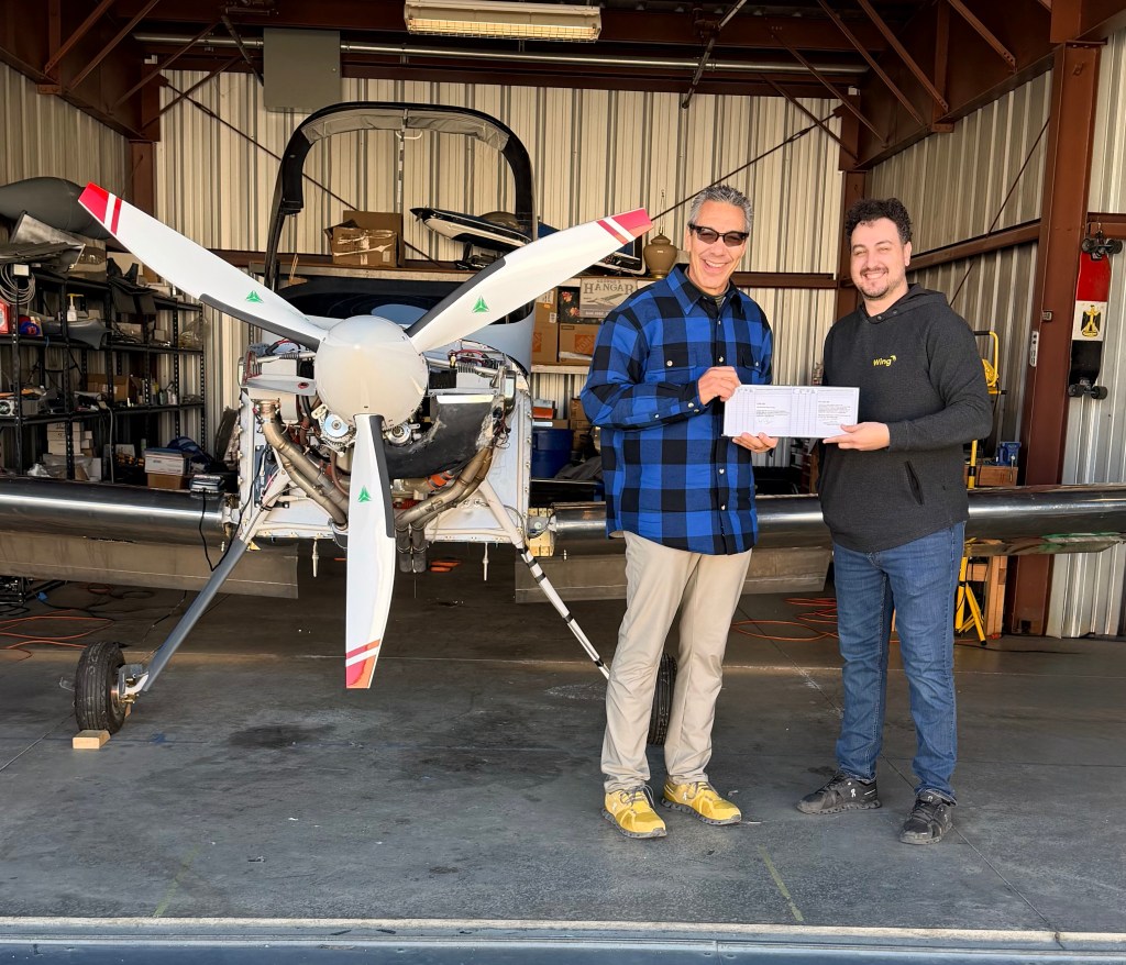
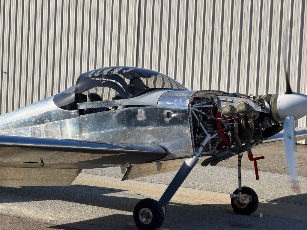
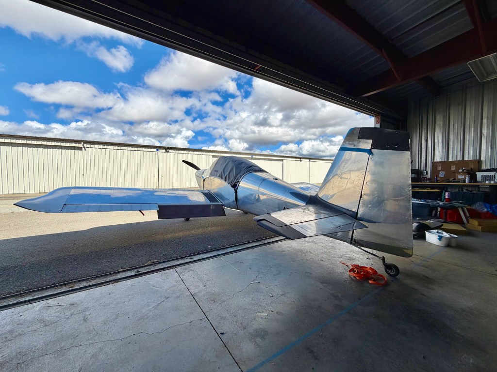
Airworthy
December 13, 2025
First Engine Run
November 9, 2025
Weight and Balance
October 20, 2025
ELT Rework + Miscellaneous tasks
August 16, 2025
Categories
Avionics
(35)
Empennage
(53)
Elevator
(16)
Fairings
(6)
Horizontal Stab
(10)
Rudder
(8)
Vertical Stab
(13)
Finishing
(83)
Canopy
(21)
Interior
(12)
Firewall Forward
(43)
Baffles
(16)
Cowling
(7)
Plenum
(6)
Propeller
(2)
Snorkel
(4)
Flying
(2)
Fuselage
(105)
General
(11)
Wings
(32)
Ailerons
(15)
Flaps
(11)
Wing Tips
(11)
Workshop
(8)
Archives
Select Month
December 2025 (1)
November 2025 (1)
October 2025 (1)
August 2025 (1)
June 2025 (1)
May 2025 (1)
February 2025 (1)
January 2025 (1)
December 2024 (1)
November 2024 (1)
October 2024 (6)
September 2024 (5)
August 2024 (1)
July 2024 (3)
June 2024 (1)
April 2024 (1)
March 2024 (2)
February 2024 (1)
January 2024 (2)
December 2023 (1)
November 2023 (3)
October 2023 (6)
September 2023 (5)
August 2023 (1)
July 2023 (1)
June 2023 (2)
May 2023 (2)
April 2023 (1)
February 2023 (1)
January 2023 (2)
October 2022 (1)
September 2022 (4)
August 2022 (4)
July 2022 (1)
February 2022 (3)
January 2022 (4)
November 2021 (1)
June 2021 (1)
February 2021 (1)
December 2020 (2)
November 2020 (1)
July 2020 (1)
May 2020 (1)
March 2020 (1)
February 2020 (1)
December 2019 (1)
April 2019 (1)
March 2019 (2)
February 2019 (1)
August 2018 (1)
July 2018 (1)
May 2018 (3)
March 2018 (4)
February 2018 (4)
January 2018 (3)
December 2017 (3)
November 2017 (4)
October 2017 (2)
September 2017 (4)
August 2017 (6)
July 2017 (3)
June 2017 (2)
May 2017 (7)
April 2017 (6)
March 2017 (3)
February 2017 (4)
December 2016 (2)
November 2016 (3)
October 2016 (2)
August 2016 (3)
June 2016 (2)
May 2016 (9)
April 2016 (3)
March 2016 (7)
February 2016 (5)
January 2016 (7)
December 2015 (10)
November 2015 (11)
October 2015 (4)
Subscribe
Subscribed
RV-7 N890GF
Sign me up
Already have a WordPress.com account?
Log in now.
RV-7 N890GF
Subscribe
Subscribed
Sign up
Log in
Report this content
View site in Reader
Manage subscriptions
Collapse this bar